The Best Guide to HVAC Electrical Wiring Diagrams & Troubleshooting (2026)
The Truth About HVAC Electrical Failures
Are you struggling to understand hvac electrical wiring diagrams when you stare at the inside of a furnace panel? You are not alone.
Ask any veteran service manager, and they will tell you a hard truth: 80% of all HVAC service calls are electrical issues. While the refrigeration cycle gets all the glory, the reality is that compressors rarely just “die” on their own. They are usually murdered by a failing capacitor, a pitted contactor, or a bad control board.
If you don’t understand the hvac electrical side of the trade, you aren’t a technician; you are just a “parts changer.” Guessing which part is broken and swapping it out costs the customer money and destroys your reputation.
In this guide, we are going to teach you how to read the map (the schematics) and how to properly test the 5 core electrical components every technician must know.
📊 Test Your Electrical Knowledge
Do you know how to test a dual run capacitor? Take a quick diagnostic quiz to see if your multimeter skills are up to standard.
How to Read HVAC Electrical Wiring Diagrams
Before you touch your multimeter, you need to read the map. Inside the access panel of almost every furnace or condenser, the manufacturer pastes the hvac electrical wiring diagrams.
These diagrams come in two main styles, and you must know how to navigate both.
1. The Ladder Diagram (The Schematic)
This is the holy grail of troubleshooting. A ladder diagram strips away what the physical wires look like and focuses purely on the logic of the circuit.
- The Structure: It looks like a ladder. The two vertical lines represent your power source (Line 1 and Neutral, or Line 1 and Line 2). The horizontal “rungs” represent individual circuits.
- The Rule: Electricity flows from left to right. It must pass through switches (like a thermostat or a high-pressure switch) before it reaches a load (like a fan motor or compressor).
- Why Use It: If a motor isn’t running, you simply trace that specific horizontal “rung” on the ladder diagram to see which switch is stuck open.
2. The Pictorial Diagram (The “Point-to-Point”)
This shows you exactly what the components look like and the physical colors of the wires connecting them.
- Why Use It: If you arrive at a job and find a rat’s nest of disconnected wires left by a previous “handyman,” the pictorial diagram tells you exactly where that yellow wire is supposed to plug into the control board.
Related: Confused by the low-voltage wires coming from the wall? Read our guide on HVAC Thermostat Wiring Color Codes.
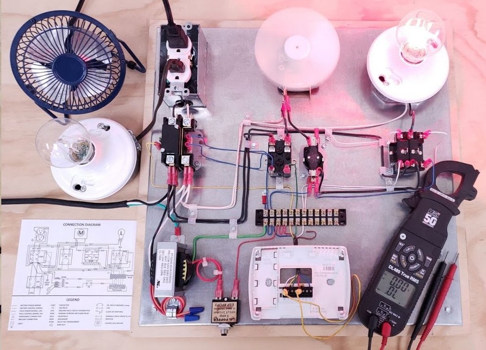
5 HVAC Electrical Components You Must Know How to Test
Once you can trace the circuit on the hvac electrical wiring diagrams, you need to test the actual components. Here are the top 5 offenders.
1. The Capacitor (The #1 Failure)
Capacitors store energy and provide the extra “kick” needed to start heavy motors like the compressor and the condenser fan. When they fail, the motor will hum but won’t spin, eventually tripping the internal overload.
- How to Test: Turn off the power. Discharge the capacitor across its terminals using an insulated resistor (never just cross them with a screwdriver). Set your multimeter to “Capacitance” (the symbol looks like -|(-). Measure across the terminals and compare your reading (in Microfarads / MFD) to the rating printed on the sticker. According to Fluke testing standards, if it is outside the +/- 6% tolerance, replace it immediately.
2. The Contactor (The Heavy Lifter)
The contactor is a heavy-duty relay. When the thermostat sends a 24V signal (low voltage) to the contactor coil, it pulls a magnetic plunger down, closing the contacts and sending 240V (high voltage) to the compressor.
- How to Test the Coil: Set your meter to Volts AC. Check the two side terminals. If you read 24V, the thermostat is calling for cooling. If the plunger doesn’t pull in, the coil is dead.
- How to Test the Contacts: Look for black, pitted, or burned contact pads. A severely pitted contactor causes a voltage drop, which starves the compressor of voltage and causes it to draw high amps.
3. The Transformer (The Power Converter)
The transformer takes high voltage from the house (120V or 240V) and steps it down to 24V to power the control board and the thermostat. If the transformer burns out (letting the “magic smoke” out), the entire system goes completely dead.
- How to Test: Check the primary (Line) side for 120V/240V. Then, check the secondary (Load) side. If you have high voltage going in, but less than 24V coming out, the transformer has failed.
4. The Control Board (The Brain)
Modern furnaces and air handlers use printed circuit boards (PCBs) to control the sequence of operation.
- How to Test: This is where your hvac electrical wiring diagrams save your life. If the thermostat is calling for heat (sending 24V to the W terminal), but the board isn’t sending 120V to the inducer motor, the board might be bad. However, always check the safety switches (like limit switches and roll-out switches) first. If a safety switch is open, the board will purposely cut the power.
5. The Blower Motor (The Lungs)
If the coil freezes solid in the summer, or the furnace trips on high limit in the winter, you often have an hvac electrical failure involving the indoor blower motor.
- How to Test: Turn off power. Disconnect the motor leads. Set your meter to Ohms (Resistance). Measure between the different speed taps and the common wire. If your meter reads “OL” (Open Loop) or infinite resistance, the internal windings of the motor are broken and the motor is dead.
🛠️ Stop Guessing, Start Diagnosing
Reading about transformers is easy. Diagnosing a broken one on an exam is hard. Practice real-world electrical faults with our interactive simulator.
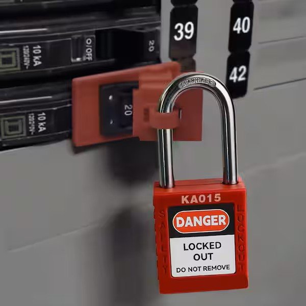
Safety First: The Lockout/Tagout Rule
We cannot talk about hvac electrical systems without talking about safety. 240 Volts is more than enough to stop your heart.
Never trust a disconnect box blindly. Just because you pulled the “pull-out” block doesn’t mean the power is fully secured. Sometimes contractors wire the line side backward, leaving the terminals live.
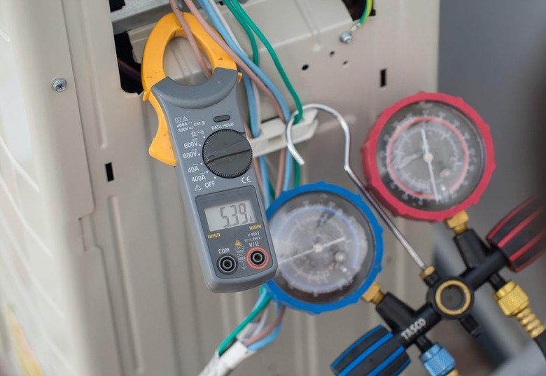
Always follow OSHA’s Lockout/Tagout (LOTO) procedures. Before touching any capacitor or motor lead, test the terminals with your multimeter set to Volts AC. Verify it is dead before you put your hands in the cabinet.
Conclusion: The Key to Passing Your Exams
Whether you are aiming for your NATE Certification or sitting for a rigorous Journeyman License, you will be heavily tested on your ability to read hvac electrical wiring diagrams.
These exams will not ask you to simply define a capacitor. They will give you a sequence of operation scenario and ask: “If switch A closes but load B doesn’t energize, where is the fault?”
To pass, you must transition from memorizing definitions to understanding the logic of the circuit.
Ready to level up your electrical skills?
Don’t wait until you are staring at a confusing schematic in the pouring rain. Build your confidence today by practicing with realistic electrical scenarios.
📱 Turn Downtime Into Study Time
Access 1,000+ advanced diagnostic and electrical calculation questions directly in your browser. Pass your certification exams with confidence.


0 Comments